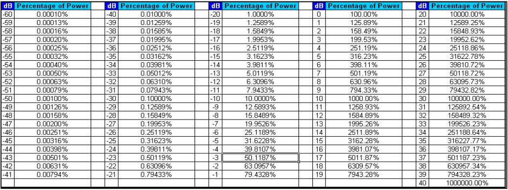
Fiber Optic Cable Coupler Loss Chart

Fiber Optic Splitter Box At Best Price In China Baymro Technology Buy Fiber Optic Splitter Box From China Import Fiber Op Splitters Fibre Optics Fiber Optic
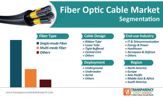
Fiber Optic Cable Market To Reach Valuation Of Us 15 Bn By 2030
Fiber Optic Couplers Selection Guide Engineering360
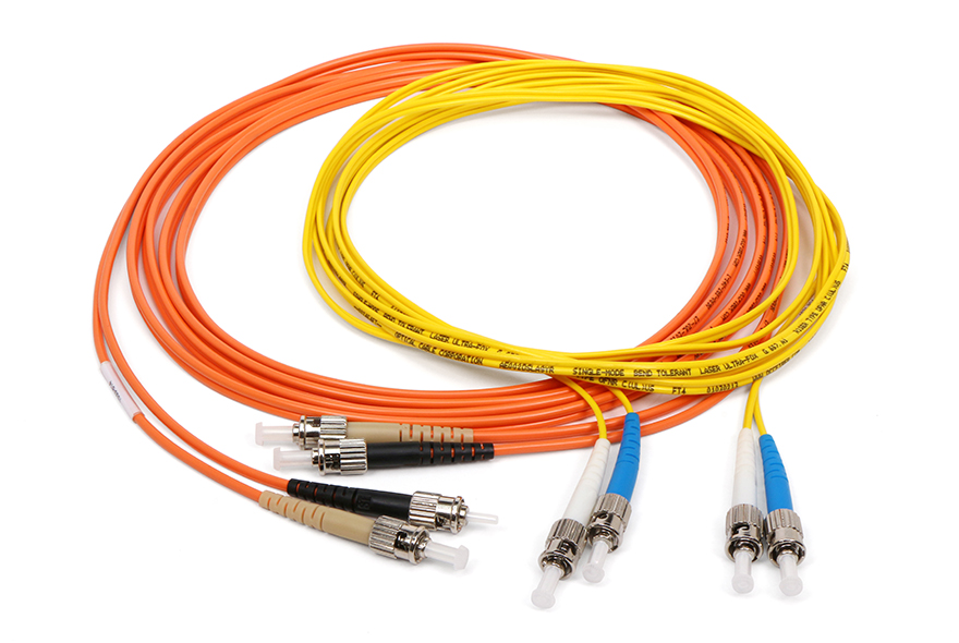
Fiber Optic Jumpers Optical Cable Corporation

12 Fiber Mtp Mpo To Lc Fiber Optic Fanout Cable Multimode Om3 Plenum Cables Plus Usa
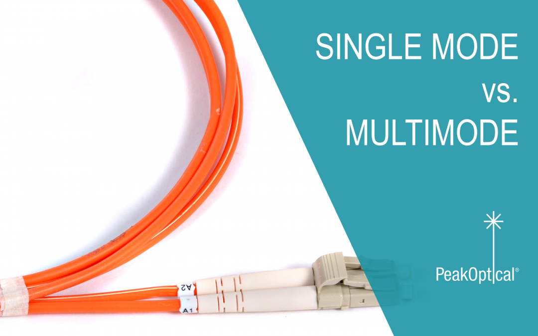
Single Mode Vs Multimode Fiber Optic Cables Peakoptical A S

1 n fiber optic splitter loss ratio chart are given bellow.
Fiber optic cable coupler loss chart.
Understanding Link Budget And Link Loss In Fiber Optic Network
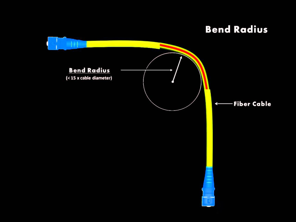
Fiber Bend Radius What S It How It Affects Fiber Cable Installation

Fiber Optic Communications For The Premises Environment By Dr Kenneth S Schneider Phd Chapter 2

Duplex Fiber Coupler St St Singlemode And Multimode Fiber Optic Cable Fiber Duplex
Source : pinterest.com
